Variable to Adapts to Any Requirement

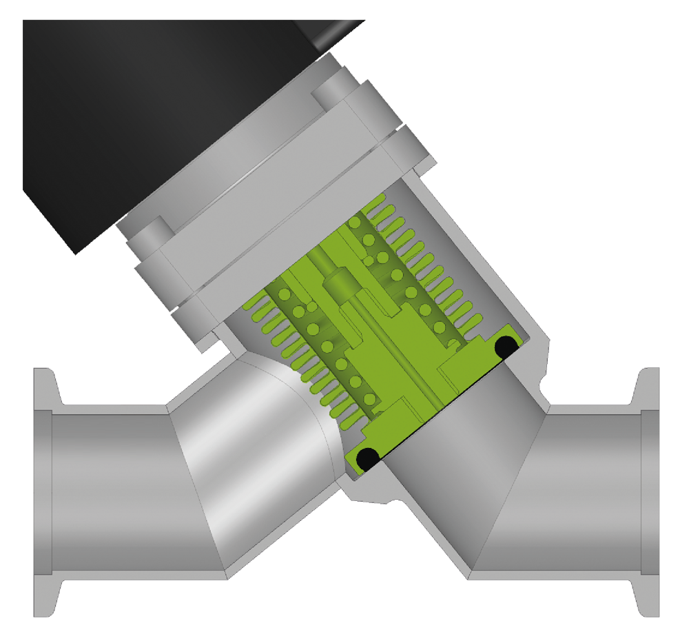
The key performance indicators for inline valves are reliability and variability. The 26.5 HV Inline Valve series delivers both. Tested in thousands of demanding applications under various process condition the 26.5 series has proven its outstanding reliability. With its various design options in actuation, flange connections, body material or sealing nearly every requirement can be met.

The 26.5 is ideal for pumping and venting of HV systems when a low outgassing rate is important. It resists high differential pressure and is fitted with a bellows-encapsulated feedthrough for particle-sensitive applications. The bellows encapsulation also prevents pressure peaks in any valve position.

Manual
Pneumatic
Electromagnetic

Closed
Open

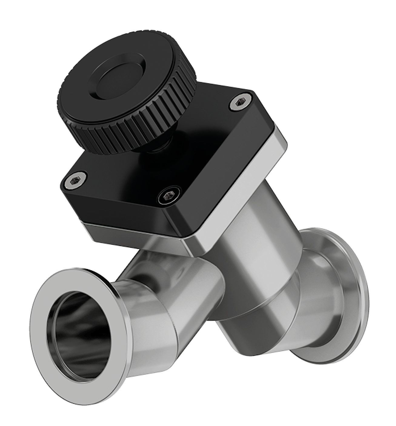
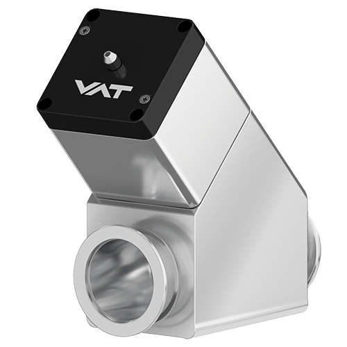
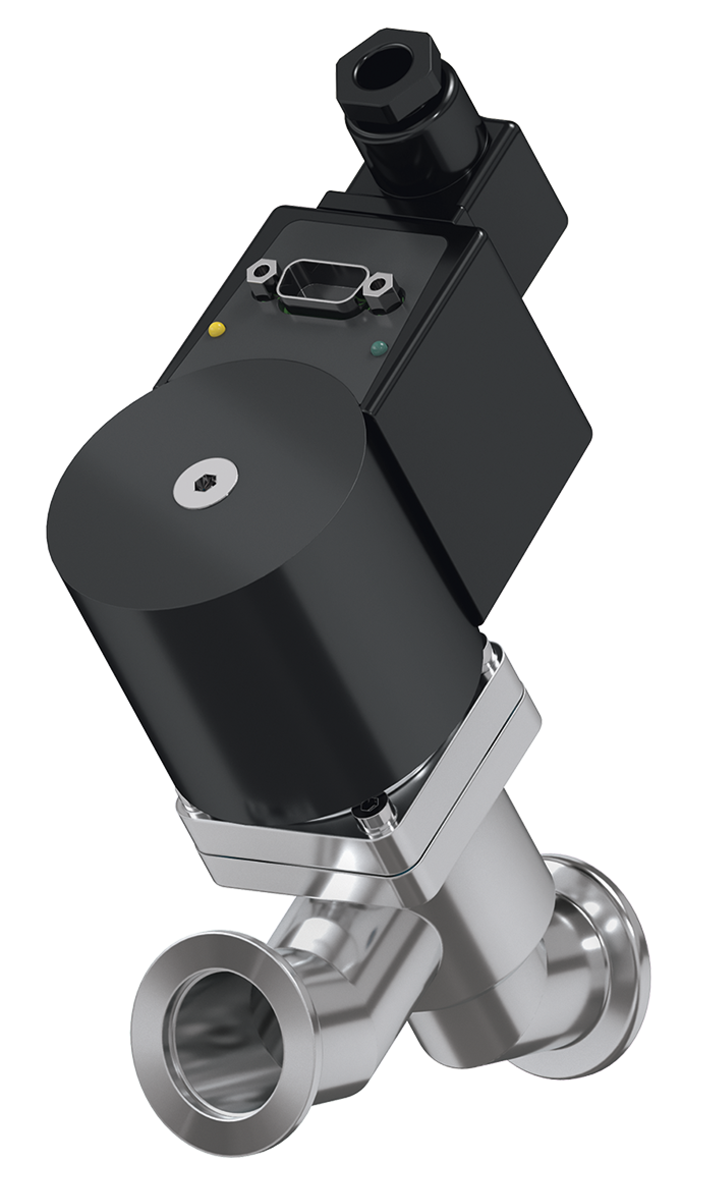
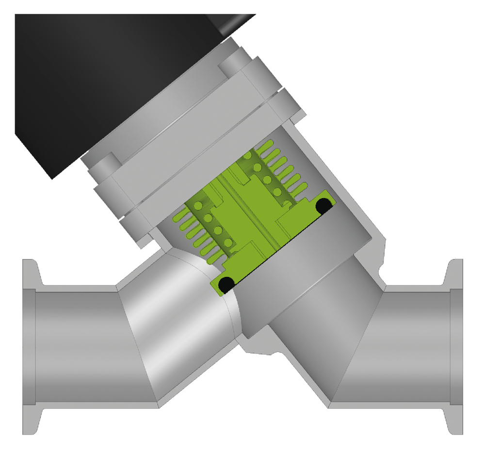
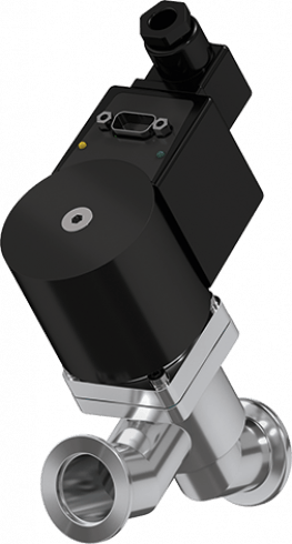
Based on a reliable and robust core design the 26.5 HV Inline Valve offers a variety of design options for actuation from manual to pneumatic and electromagnetic. In sizes from DN 10 to DN 160 mm (0.4" – 6.4") the 26.4 can be selected in aluminum or stainless steel in various specifications. The standard options for flange connectors are ISO-KF and ISO-K.

A visual position indication comes as standard although an electrical indicator can be added as an option. The valve can be controlled by a solenoid valve either “on board” or in a distant location if required. The 26.5 can be used in different temperature regimes depending on the sealing elastomer chosen. The valve can be supplied as normally opened (NO), normally closed (NC) or double acting. In addition to these standard options further customization is possible.


Key features of the 26.5 HV Inline Valve

Features:

  • Large number of design options
  • Resistance against high differential pressure
  • Long maintenance free cycle

Benefits:

  • Outstanding reliability
  • Adjustable to various requirements

Technical data
Sizes (DN)
10 mm (⅜")
16 mm (⅝")
25 mm (1")
40 mm (1½’’)
50 mm (2")
63 mm (2½")
80 mm (6")
Actuator
Manual/Pneumatic Actuator
Pneumatic, single acting opening spring
Pneumatic, single acting closing spring
Pneumatic, double acting
Manual, removable handwheel
Electromagnetic Actuator
Electromagnetic with Closing Spring (NC)
Pneumatic, single acting closing spring
Body material
Aluminum; Stainless steel
Feedthrough
Bellows
Standard flanges
ISO-KF
ISO-K
Leak Rate
Valve body
< 1 × 10⁻⁹ mbar ls-1
Valve Seat
< 1 × 10⁻⁹ mbar ls-1
Pressure range
Pressure range
1 × 10⁻⁸ mbar to 5 bar (abs)
Manual/Pneumatic Actuator
DN 10– 50
1 × 10⁻⁸ mbar to 5 bar (abs)
DN 63 – 80
1 × 10⁻⁸ mbar to 2.5 bar (abs)
DN 100– 160
1 × 10⁻⁸ mbar to 2 bar (abs)
Electromagnetic Actuator
DN 10– 40
1 × 10⁻⁸ mbar to 2 bar (abs)
Differential Pressure on Plate
In opening direction
DN 10 – 50
≤ 5.0 bar
DN 63 – 160
≤ 1.2 bar
In closing direction
DN 10 – 50
≤ 5.0 bar
DN 63 – 80
≤ 4 bar
DN 100– 160
≤ 2.0 bar
Electromagnetic Actuator
DN 10– 40
≤ 5.0 bar
Differential pressure at opening
≤ 1 bar
Cycles until first service
Manual Actuator
DN 10 – 160
≥ 3 Million
Pneumatic Actuator
DN 10 – 80
3 million (NC, NO)
Electromagnetic Actuator
DN 100 – 160
1 Million
(NC, double acting) 
Actuator
DN 10 – 40
200 000
Temperature
Valve body
Manual/Pneumatic Actuator
≤ 150 °C
Electromagnetic Actuator
≤ 50 °C
Actuator
Manual/Pneumatic Actuator
≤ 120°C
Electromagnetic
≤ 50 °C
Solenoid Valve & Position Indicator
≤ 80 °C
DN 10 – 80
≤ 50 °C
(DN 100 – 160)
Material
Aluminium 
EN AW-6060 (3.3206)
EN-AW-6061 (3.3211)
(DN 16 – 63)
EN AW-6063 (3.3206)
EN AW-6082 (3.2315)
EN AC-42000
DN 80 – 160
Stainless Steel
AISI 304 (1.4301)
(DN 10 – 50)
AISI 316L (1.4404, 1.4435)
(DN 63 – 160)
plate
AISI 316L (1.4404, 1.4435)
Bellows
AISI 316L (1.4404, 1.4435)
AISI 316Ti (1.4571)
Seal
Bonnet
FKM
plate
FKM
Mounting position
Any
Solenoid valve
DN 10 – 80
24 VDC, 2.5 W (others on request)
DN 100 – 160
24 VDC, 1.0 W (others on request)
Position indicator: contact rating
Voltage
Manual/Pneumatic Actuator
≤ 50 VAC/DC
Electromagnetic Actuator
max. 48 VAC / DC
Current
Manual/Pneumatic Actuator
5 – 100 mA
Electromagnetic Actuator
max. 500 mA
Mains Voltage
100 – 120 V / 200 – 240 V / 50 – 60 Hz
Operating frequency
max. 15 min-1 at 20°C
Valve position indication
Visual (mechanical)
Scroll to:
Scroll to:
Specify standard product

Get to the product details to specify your requirements to get a quote or to get a specific CAD data download.

Customized Solution

Specify your customized solution.

If you have your specification already at hand, please upload it and submit it to us. We are happy to send you a quote.

Selected Applications

Explore all applications