Sub-Fab Systems
Sub-fab processes can be challenging: corrosive, abrasive, and toxic gases and/or condensation and high levels of by-products in the gas stream can al...
Read more
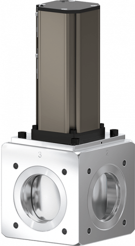
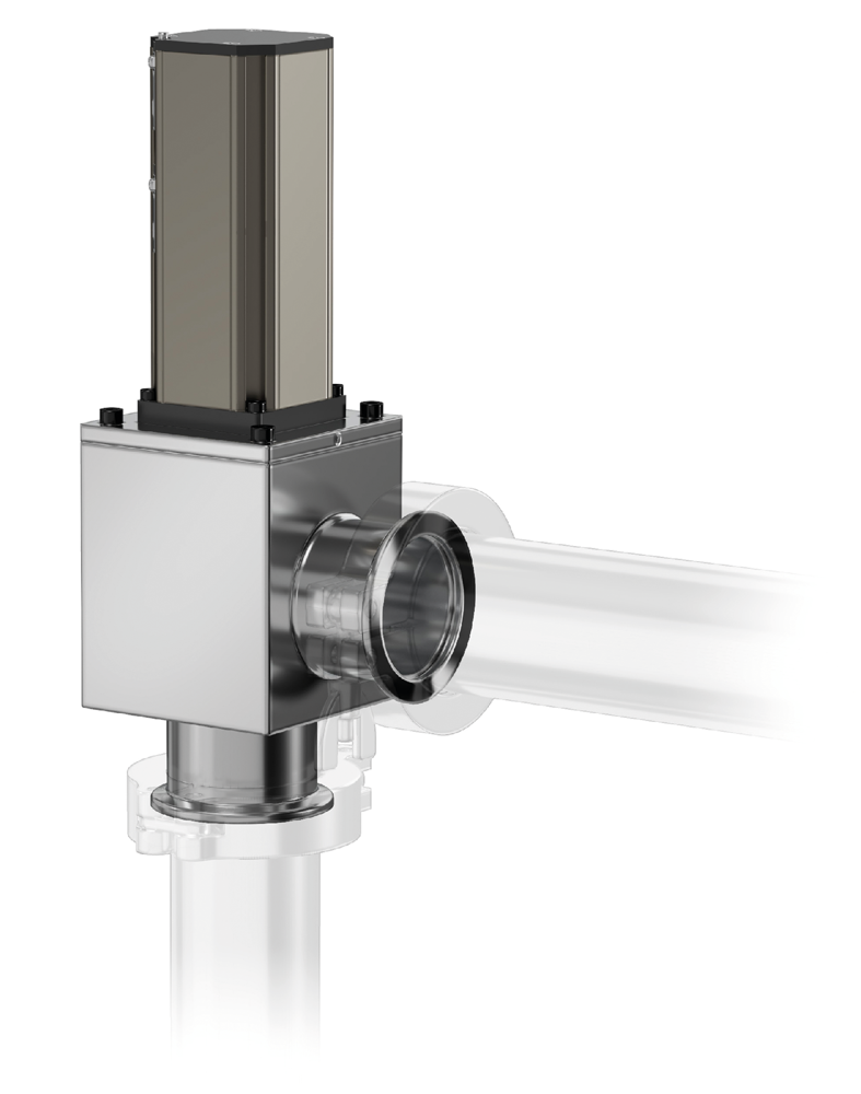
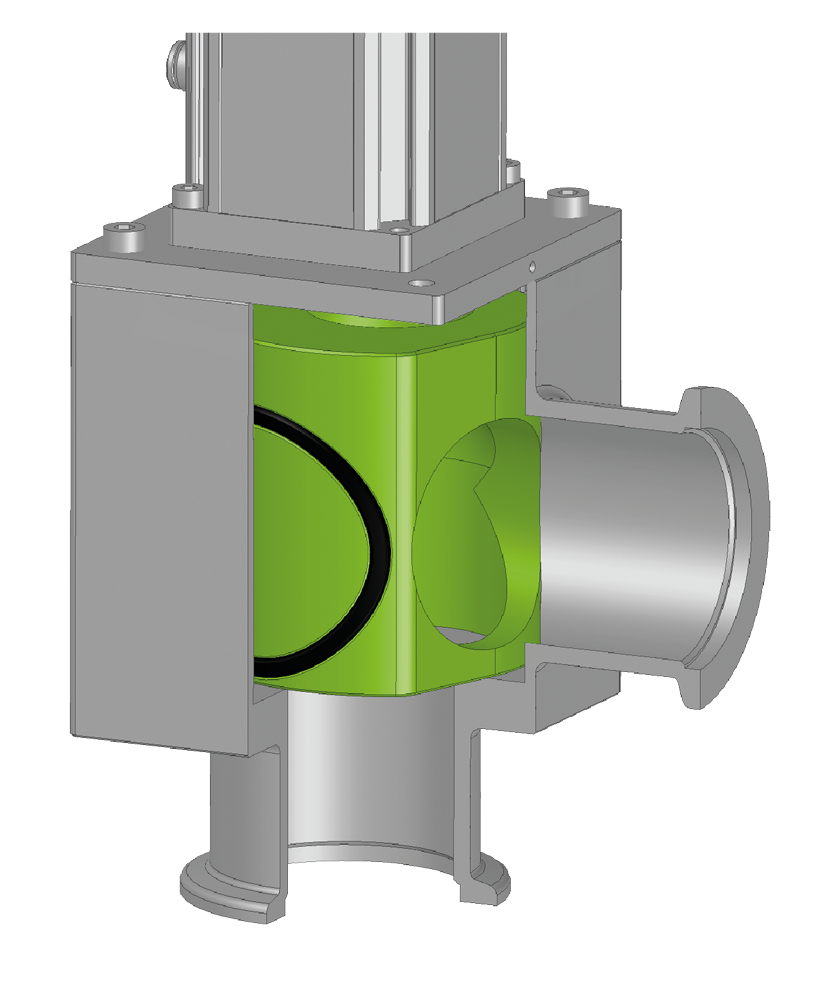
The 25.2 HV Cylinder Valve series is designed to be used in harsh process environments with corrosive and particle carrying gasses, such as sub-fab processes. The series is available in angle (25.0), inline (25.1) and 3/2 way design (25.2) and is laid out in each version for maximum conductance.
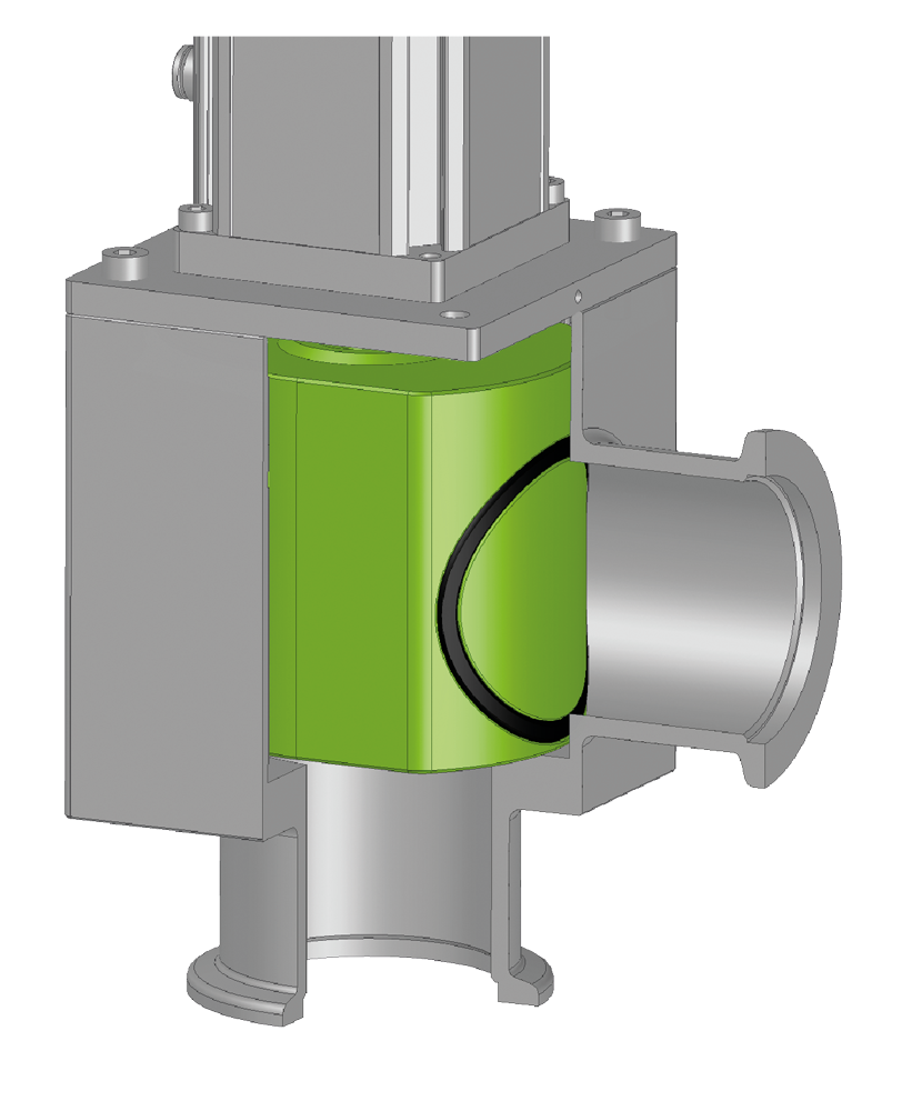
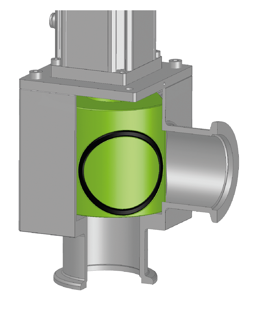
To provide durability and high uptime the 25.2 HV Cylinder Valve series has a seal protection system that combines the benefits of the high conductance of a cylinder design with an increased seal lifetime. The seal protection system works with a TILT-TURN-TILT movement of the cylinder in which the cylinder removes the gate seal from the valve seat in a lift movement, avoiding any friction and with it higher seal wear and particle generation. When at full opening (after a 90° turn), the TILT-TURN-TILT movement will also press the seal gently to the valve body to protect the seal also from potential abrasive particles in the gas stream. If there is power failure, the valve mechanism is locked in its open or closed position, maintaining the last valve position.
Already installed in thousands of demanding applications under various process conditions, the 25.2 HV Cylinder Valve series has proven its outstanding reliability.
25.2 HV Cylinder Valves are available as a pneumatic version with a solenoid valve as an accessory for external mounting. The valve position is indicated by an LED (10 – 30 VDC, 5 – 100 mA).
Standard options for flange connectors are ISO-KF and ISO-KF “claw”. The standard gate sealing is FKM. Customer-specific flanges can be integrated, as can special features, e.g., heating cartridges, other sealing material or a stainless steel version.
Features:
Benefits: