
Pressure Controller Options for Mechatronic Vacuum Valves
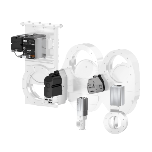
Integrated or external pressure controller for VAT mechatronic vacuum control valves offer a wide range of configuration options.
They convince through ...
- Very short response times
- Fast and precise pressure control
- Precise valve position control
- Learning algorithms for automated control optimization
- Digital and analog inputs for sensor signals
- Choice of local or remote control
- Integrated display for local status indication
Learning Algorithms for Automated Control Optimization
With the integrated learning function, the pressure controller independently adapt the valve control to the prevailing process conditions within defined limits. This increases the effectiveness of the valve control in terms of speed, conductance, and the avoidance of vibrations and shocks.
By operating the LEARN function – only needs to be performed once during start-up – the relevant system parameters are determined automatically. Due to the adaptive algorithm, the pressure regulator continuously adjusts to changes in gas flow or gas type, ensuring optimal pressure control at all times.
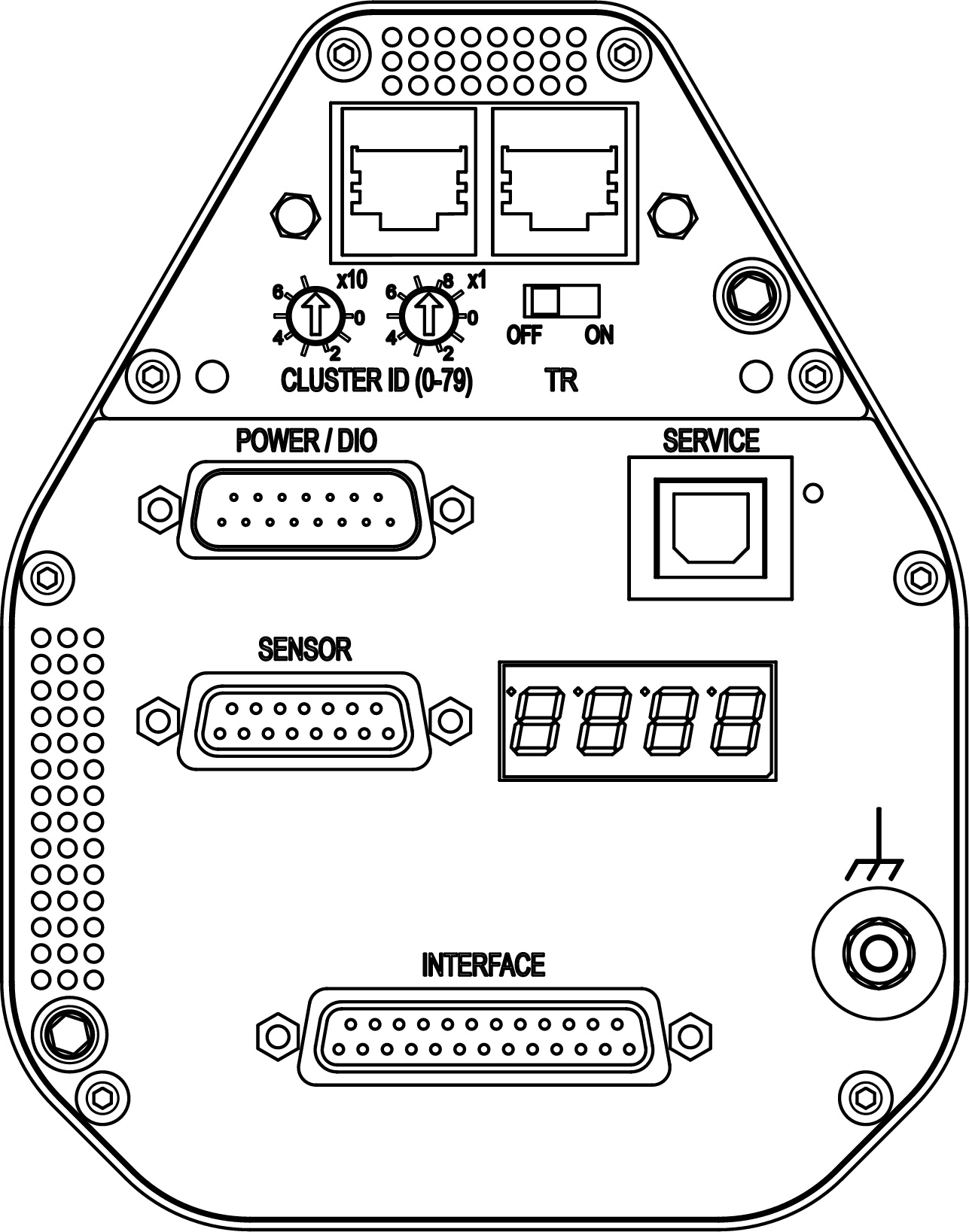
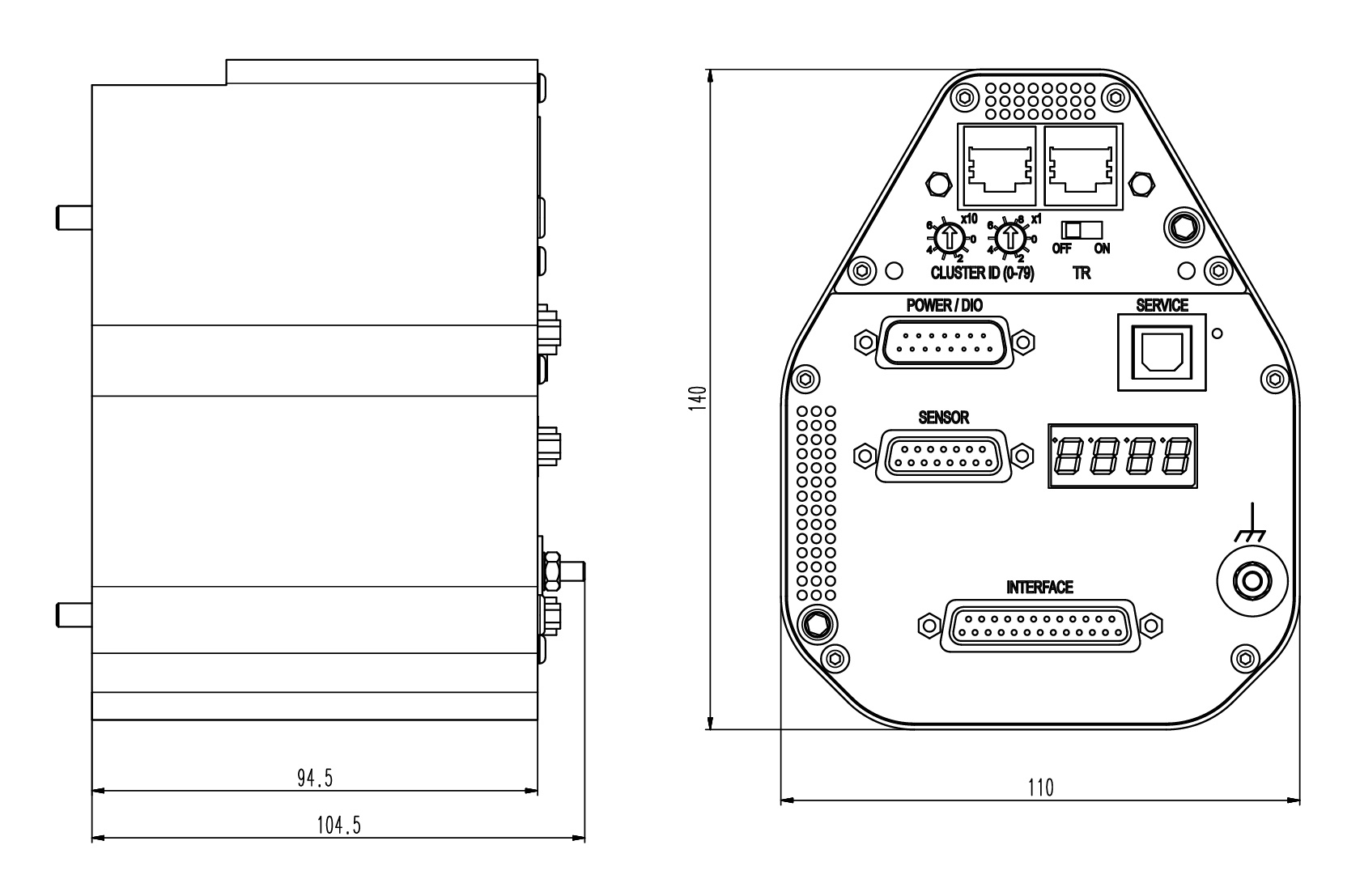
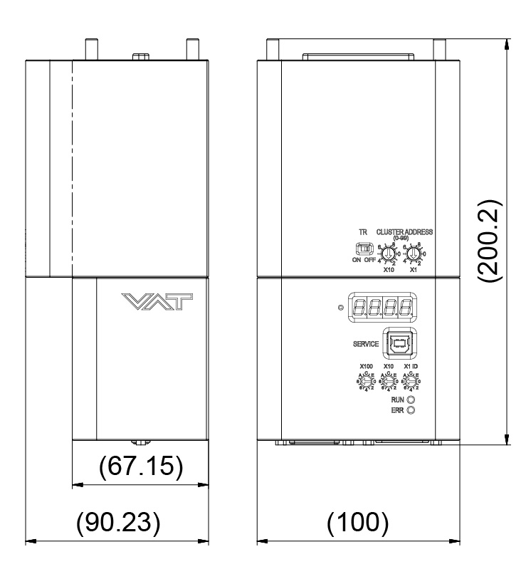
In position control mode, the valve plate can be moved to any position. Status and position are indicated via the 4-digit display.
VAT pressure controllers can be controlled with an external PC via Logic, RS232, RS485, DeviceNet®, Ethernet, Profibus, CC-Link or EtherCAT interface. For this purpose, VAT offers special configuration, control and diagnostic software for Windows, which is automatically loaded when a PC is connected to the controller.
The RS232 interface and the fieldbuses can also be used for digital signal input to close and open the valve. In addition, digital outputs are available for the signals "closed" and / or "open".
The control via the logic interface can be done optionally via digital and analog signals.
Since the pressure controllers are each designed for specific vacuum valves, you must first identify the corresponding valve type to find out which options are available for this valve type.
Technical Data
Integrated Controller for the Series 61.3, 61.6, 61.7, 95.3
Available interfaces:
- Logic
- RS232
- RS485
- DeviceNet®
- Ethernet
- Profibus
- CC-Link
- EtherCAT
| Power consumption – Controller + motor – Power failure option (PFO) – Sensor power supply (SPS) | 24 V DC (±10%) @ 0.5 V pk-pk max. 40 W max. 10 W max. 36 W |
| Sensor supply | 24 V DC or ±15 V DC |
| Sensor input – Signal voltage – Input resistance – Resolution – Sampling rate | 0 – 10 V DC linear with pressure Ri = 100 kΩ 0.23 mV 10 ms |
| Control accuracy | 5 mV or 0.1% of setpoint (the higher value applies) |
| Position resolution | depending on valve type |
| Protective system | IP 30 |
| Temperature – Valve Body – Controller | ≤ 120 °C (Series 61.6, 95.3) ≤ 150 °C (Series 61.3, 61.7) max. 50°C (≤ 35 °C recommended) |
Integrated Controller for the Series 62.0, 64.8, 67.0

Available interfaces:
- Logic
- RS232
- RS485
- DeviceNet®
- Profibus
- EtherCAT
| Power consumption – Controller + motor – Power failure option (PFO) – Sensor power supply (SPS) | 24 V DC (±10%) @ 0.5 V pk-pk max. 150 W max. 10 W max. 40 W |
| Sensor supply | 24 V DC or ±15 V DC |
| Sensor input – Signal voltage – Input resistance – Resolution – Sampling rate | 0 – 10 V DC linear with pressure Ri = 100 kΩ 0.23 mV 2 ms |
| Control accuracy | 5 mV or 0.1% of setpoint (the higher value applies) |
| Position resolution | depending on valve type |
| Protective system | IP 40 |
| Temperature – Valve Body – Controller | ≤ 80 °C (Series 62.0, 64.8) ≤ 120 °C (Series 67.0) max. 50°C (≤ 35 °C recommended) |
Integrated Controller for the Series 64.2
Available interfaces:
- Logic
- RS232
- RS485
- DeviceNet®
- Ethernet
- Profibus
- CC-Link
- EtherCAT
| Power consumption – Controller + motor – Power failure option (PFO) – Sensor power supply (SPS) | 24 V DC (±10%) @ 0.5 V pk-pk max. 54 W max. 10 W max. 36 W |
| Sensor supply | 24 V DC or ±15 V DC |
| Sensor input – Signal voltage – Input resistance – Resolution – Sampling rate | 0 – 10 V DC linear with pressure Ri = 100 kΩ 0.23 mV 10 ms |
| Control accuracy | 5 mV or 0.1% of setpoint (the higher value applies) |
| Position resolution | depending on valve type |
| Protective system | IP 20 |
| Temperature – Valve Body – Controller | ≤ 150 °C max. 50°C (≤ 35 °C recommended) |
Integrated Controller for the Series 65.3
Available interfaces:
- Logic
- RS232
- RS485
- DeviceNet®
- Ethernet
- Profibus
- CC-Link
- EtherCAT
| Power consumption –Controller + motor – Power failure option (PFO) – Sensor power supply (SPS) | 24 V DC (±10%) @ 0.5 V pk-pk max. 50 W max. 10 W max. 36 W |
| Sensor supply | 24 V DC or ±15 V DC |
| Sensor input – Signal voltage – Input resistance – Resolution – Sampling rate | 0 – 10 V DC linear with pressure Ri = 100 kΩ 0.23 mV 10 ms |
| Control accuracy | 5 mV or 0.1% of setpoint (the higher value applies) |
| Position resolution | depending on nominal diameter |
| Protective system | IP 20 |
| Temperature – Valve Body – Controller | ≤ 120 °C max. 50°C (≤ 35 °C recommended) |
Integrated Controller for the Series 65.5
Available interfaces:
- Logic
- RS232
- RS485
- DeviceNet®
- Profibus
- EtherCAT
| Power consumption – Controller + motor – Power failure option (PFO) – Sensor power supply (SPS) | 24 V DC (±10%) @ 0.5 V pk-pk max. 110 W max. 10 W max. 40 W |
| Sensor supply | 24 V DC or ±15 V DC |
| Sensor input – Signal voltage – Input resistance – Resolution – Sampling rate | 0 – 10 V DC linear with pressure Ri = 100 kΩ 0.23 mV 2 ms |
| Control accuracy | 5 mV or 0.1% of setpoint (the higher value applies) |
| Position resolution | depending on nominal diameter |
| Protective system | IP 40 |
| Temperature – Valve Body – Controller | ≤ 120 °C max. 50°C (≤ 35 °C recommended) |
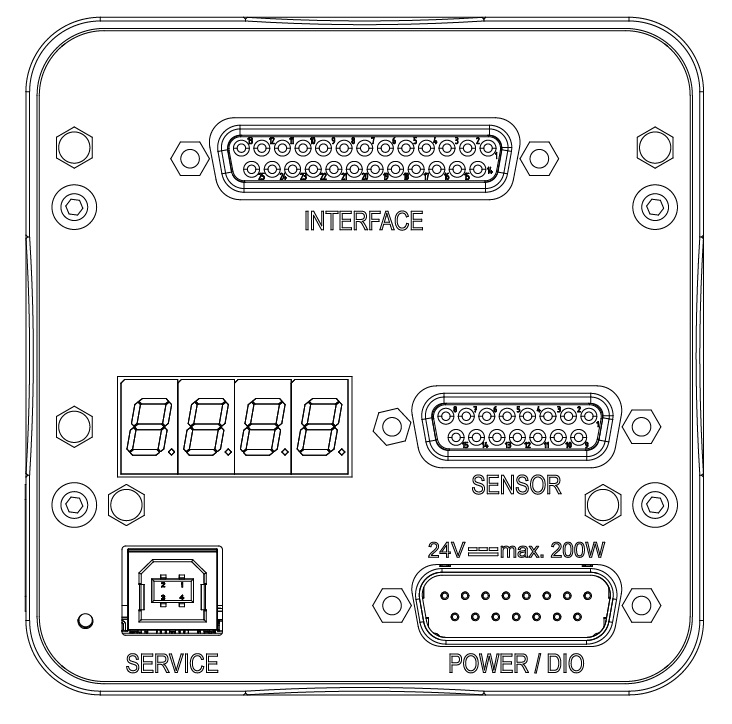
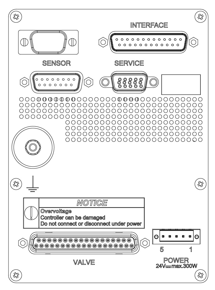
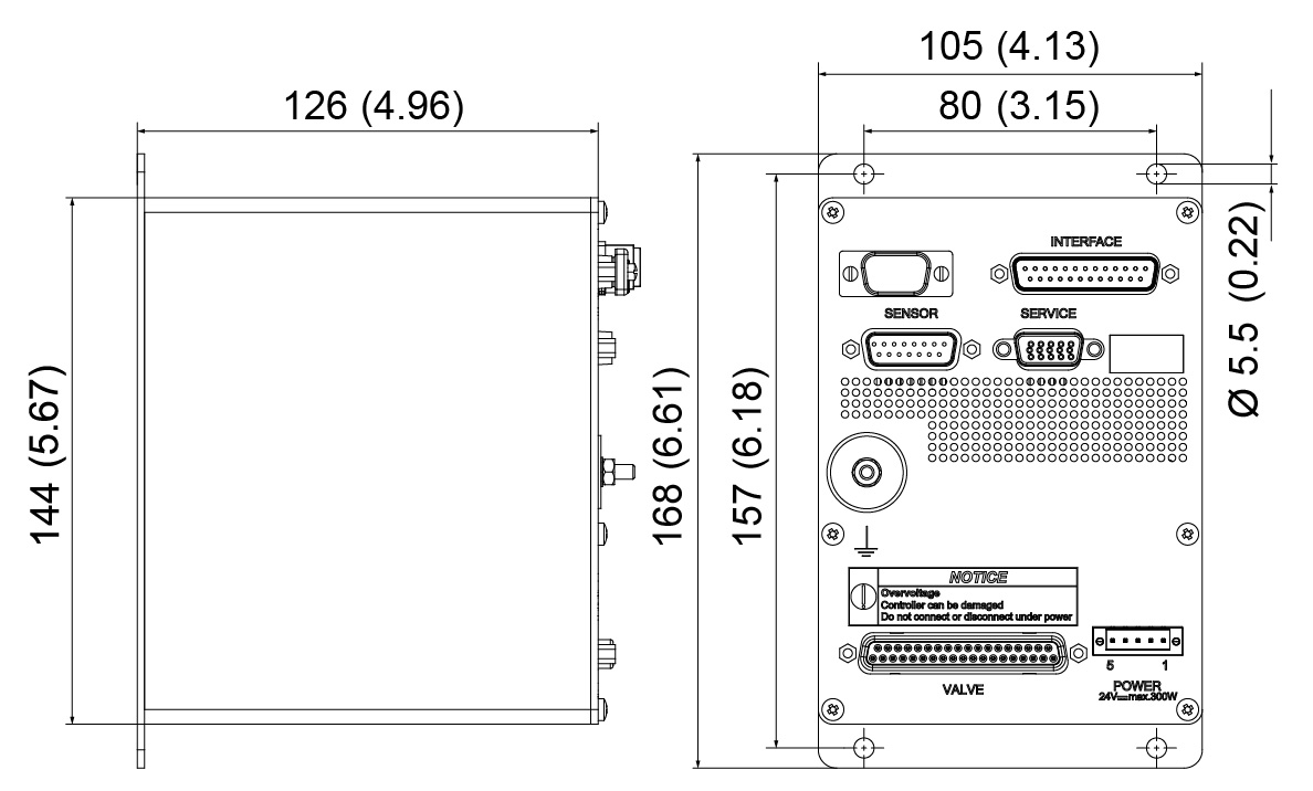
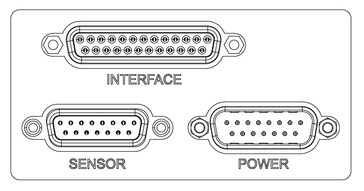
Electrical Connections
| CONNECTION | TYPE | |
| POWER | Series 61.3, 61.6, 61.7, 95.3, 62.0, 67.0, 64.8, 65.3, 65.5 64.2 | DB-15 male Weidmüller SL 3.50 male |
| SENSOR | Sensor input Sensor power supply | DB-15 female |
| INTERFACE | Logic, RS232, RS485 Ethernet (with Logic I/O) DeviceNet® (with Logic I/O) Profibus (with Logic I/O) CC-Link (with Logic I/O) CC-Link (with Logic I/O) 64.2 EtherCAT (with Logic I/O) | DB-25 female RJ 45 Micro-style M12 male DB-9 female DB-9 female 5-pole screw terminal 2 RJ 45 |
| Logic I/O | Series 61.3, 61.6, 61.7, 95.3, 62.0, 67.0, 64.8, 65.3, 65.5 64.2 | DB-15 male Binder M8 female |
| SERVICE | Connector: all except below 64.2 | USB type B DB-15 HD female |
Additional Options
| Sensor Power Supply (SPS) | ±15V DC |
| Power Failure Option (PFO) | Valve opens/closes in defined way automatically |
| Valve Cluster | Synchronically control of several valves in master slave mode |
Accessories
- Control Performance Analyzer (CPA)-Software
- Service Box
- Control Panel
- Connector kit for various interfaces
- Power supply unit (input 100- 240 V AC, output 24 V DC / 4 A)
Calibration, Control, Analysis
via PC
Valve calibration and control via PC using the CPA software provided by VAT is very simple and intuitive. The following functions are provided:
- Setup
- Operation
- Monitoring
- Diagnostics
- Graphical visualization of pressure behavior
- Programming of control profiles
- Recording of control sequences
- Several options for data analysis and process optimization
via Service Box and Control Panel
For simplified handling, calibration, control and analysis is also possible via a service box and a control panel integrated in a standard 19" rack. The range of options is comparable to the PC version, only the data visualization is limited due to the compact design and the simplified display.